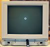
This is a Symbolics Model PE36-PCONS, Part No 365404 Rev C console. My serial number is 21811. ("There are many like it, but this one is mine.") An album of detailed internal photographs is available including full size versions of all the below images.
The console seems to be in good shape, with all electrolytic capacitors intact (not bulging or leaking). I should probably test the power supply outputs as there are trimmers for the voltages to adjust them.
Functionally it seems to work properly. The picture is not great (I don't know how to use the adjustments to improve it) but it's adequate. The console cable/connector at the back is a bit temperamental; if it's not held on just correctly the monitor makes an unhappy noise and the display doesn't show properly.
Details
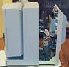
To open the console, you simply remove four flat-head screws from the back and slide it out. This reveals an L-shaped chassis.
There are three boards on the L-shaped chassis:
- Symbolics, Inc. Console Controller
- PCBA 170600
- Rev. P S/N 1146
- Copyright 1987, Made in USA
- QCI Type 2, 1691
- Symbolics, Inc. 3620 Deflection Board
- PCBA 170606
- Rev D (or O, my sticker is cut off)
- S/N 660 (also etched in the PCB)
- Todd Products Corp - Power Supply
- Model: 5XS9216A
- Input: 200W
- Serial No 8082804
There are four connections from this to the CRT and its controller card, the "Video Amp":
- Chassis ground
- J113 on Console Controller, a 4-wire connection that seems like a signal
- J4 from the Deflection Board, a 6-pin thick set of wires
- J2 from the Deflection Board, a 12-pin thick set of wires
Additionally, there is a power distribution cable of 15 pins that goes from the power supply to the other two PCBs. Only 12 of those pins are connected on the power supply, though.
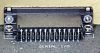
Finally, the Console Controller and the Deflection Board meet in the corner with a connector labeled AMP 532548-3 9110.
The controller card on the back of the CRT is difficult to remove, so I didn't get great pictures of it and then only with a cell phone camera.
- Video Amp Bd
- Symbolics Inc.
- Copyright 1987
- PCBA 170609 with REV or S/N on front
- PCB 170608 REV 3 on back with stickers:
- REV G
- S/N 1115
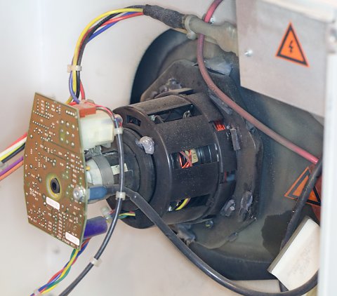
Finally, there is a box into which the CRT flyback voltage goes, and with other leads to the Video Amp board and the Deflection Controller.
Power Supply
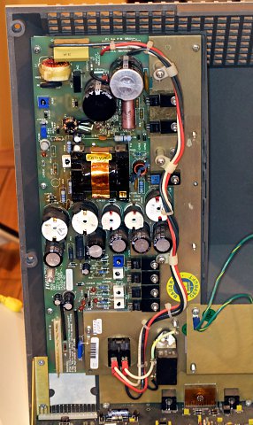
On the power supply, there is a large metal cover that can be removed with two screws and two nuts to reveal the transformer plus five pairs of a capacitor and inductor.
The power supply has 12 electrolytic capacitors. One of these (C7, a pink axial capacitor) I'm not actually sure exactly what it is. All seem to be in good condition with no obvious bowing of the tops or leaks.
There are seven trimmers:
- R39
- R35 +5V ADJ
- R46
- R12 +24V ADJ
- R7 +50V ADJ
- R20 -15V ADJ
- R17 +15V ADJ
There is a large heat sink on one end of the board with seven transistors bolted to it.
3620 Deflection Board
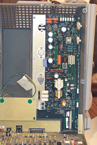
This is where the CRT picture is adjusted. There are ten trimmers, eight tiny ones and two large ones. TODO: LINK TO OTHER PAGE
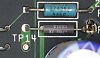
There are quite a few Test Points labeled TP#, as well as a few odd test-point like things:
- COM1 50V RET
- COM2 24V RET
There are also two large and two small power transistors mounted on a huge heat sink.
There are 12 electrolytic capacitors. On mine, they all appear intact. Two have an odd label that reads 33 uF 200V but with spaces between the two 3's. They are the same size as other 470 uF, 63V caps, so maybe they are just 33 uF.
Console Controller
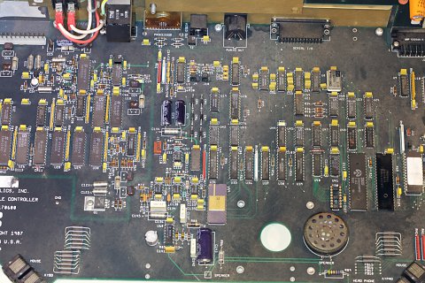
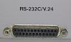
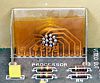
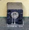
On the rear of the monitor, all the inputs (but power) come in to this board:
- Video in
- Video out
- Processor
- Audio out
- Serial I/O
![]()
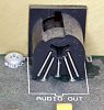
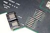
The Symbolics keyboard and mouse both connect to this board on either side, and there is a headphone connector on the right side as well. I wonder if two mice or keyboards could be attached simultaneously.
There is a speaker on this board. It can be made louder and quieter with LOCAL-L and LOCAL-Q.

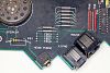
There are 8 DIP switches with no label as to what their purpose is. From switch 1-8 mine are 01110001.
There are several jumpers:
- J9, J10 - 2x3 pin with jumpers on four of the six pins
- J11 - two pin
- J12 - three pin with a jumper on two
There is one thing that looks like a trimmer, R26.
There is an unpopulated 2x8 DIP socket, U50, and two unpopulated 2x10 positions labeled U10/SP1 and U11/SP2.
Video Amp Board
There is one electrolytic capacitor on it, a navy blue one with values 85ºC 47uF 160V that was extremely hard to read with a little mirror. It seems to be intact.
This board has thick wire connections to the little voltage box and the deflection board, and one small 4-pin connection to the console controller board.
CRT
I couldn't see much about the CRT itself. It has two labels on the back that I could see with nothing comprehensible. One says "897PAN", and the other says "1".
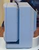
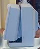
The CRT is housed in a case that allows it to swivel vertically when a release is pushed on the right side of the case (looking at the front of the CRT).
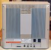
The outer box of the console is mounted on a swivel that has about 180 degrees of travel.
Voltage Box
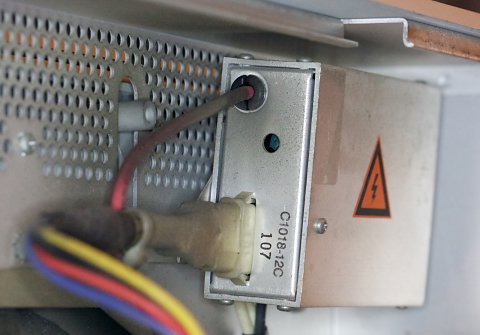
I couldn't see anything written on this box except for a large electrical warning sign. I am guessing it's a flyback transformer.
Miscellaneous
There are at least five missing screws or nuts in my console interior. One of the chassis ground terminals was not connected to anything; perhaps it was supposed to be connected to the screw without a nut on it.
Defects Noted
While reviewing the pictures taken for this story, I noticed these things that should be examined more closely:
- Deflection Board: Terminal of R31 has something on it, maybe the nearby C4X has leaked?
- Bottom of the right (?) keyboard jack on the Console Controller card, those six pins look to still have resin on them. Perhaps the jack was repaired but the flux was not washed off.
Cable Notes
Sometimes when I use the console, it doesn't show a clean picture and it makes a sickening electronic noise as well. Turns out the console cable is very susceptible to short circuits, and you must be very careful handling it and plugging it in. Per David K. Schmidt:
You have to be careful not to twist the connector on the cable in the opposite direction of the cable. This can cause a short in the connector and exhibit the behavior you described. I always twist the cable, not the connector when I am attaching the cable to the console or the computer.